
As integrated circuits (ICs) pack more transistors into smaller nodes, thermal management has become a first‑order design challenge. Heat isn’t just a comfort issue—it directly impacts reliability, performance, and product lifespan. In this article, I’ll break down where heat comes from inside ICs, what happens when temperatures rise, and the practical models and data mechanical engineers can use to predict and control IC temperatures.
What’s Inside an IC (and Why It Matters)
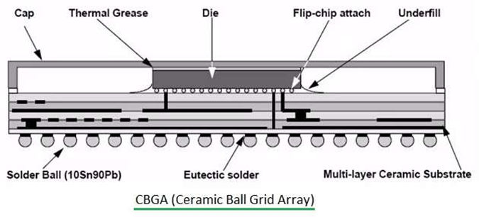
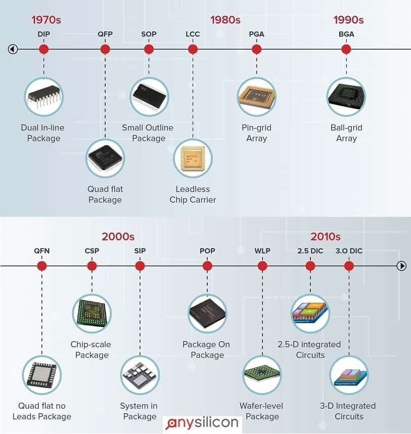
Most IC packages share a familiar stack: a substrate (PCB or interposer), the silicon die, a lid or case, and a thermal interface material (TIM)—with numerous variations like PBGA and FC‑BGA that trade off cost, performance, and manufacturability. Understanding this physical architecture is the first step to modeling heat flow paths from die to ambient.
Where IC Heat Comes From
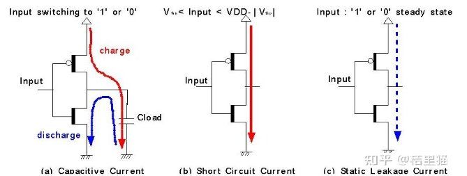
IC power dissipation typically falls into two buckets: dynamic and static.
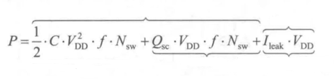
- Dynamic Power combines switching losses (charging/discharging internal and net capacitances) with short‑circuit losses that occur as gates transition and momentarily connect supply to ground.
- Static Power is dominated by leakage currents when circuits are inactive. As technology scales to advanced nodes (e.g., 5 nm, 3 nm), leakage becomes a major contributor, pushing baseline temperatures higher.
What Happens When ICs Overheat
High temperature triggers a cascade of effects that span mechanics, chemistry, and electronics:
- Thermo‑mechanical stress & strain: Dissimilar materials bonded together (different CTEs) accumulate stress with thermal cycling, risking permanent package damage.
- Corrosion & electro‑chemical reactions: Moisture and contaminants, under electric fields, accelerate surface and interconnect degradation.
- Oxide decomposition: Elevated temperatures speed up material breakdown within the stack.
- Runaway power: Leakage rises with temperature, increasing static power and creating a positive feedback loop.
- Electrical impacts: Timing delays, electromigration, and reduced life span can follow, ultimately threatening functional correctness.
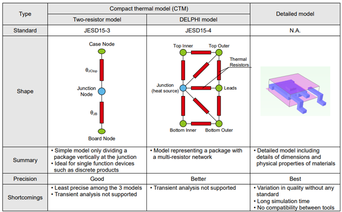
Modeling IC Temperature: The Two‑Resistor Approach
A widely used compact representation of IC thermal behavior is the Two‑Resistor Model, which partitions heat flow into junction‑to‑board (θJB) and junction‑to‑case (θJC) paths for system‑level estimation and power‑temperature calculations. Industry measurements reference JEDEC JESD51‑8 (θJB) and JESD51‑14 (θJC). These standards provide consistency, but remember: θJB can be sensitive to the measurement method and may not perfectly reflect real assemblies. Use them as informed estimates, not absolute truths.
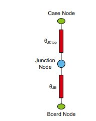
With θJB and θJC, engineers can quickly estimate junction temperatures from known board, case, or ambient conditions and back‑calculate allowable power under given cooling constraints—useful early in concept studies and for scoping heatsink or airflow needs.
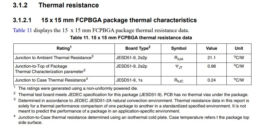
Getting Thermal Resistance Data
You have two primary sources:
- IC datasheets/specs — Many vendors publish θJA/θJB/θJC values and test conditions.
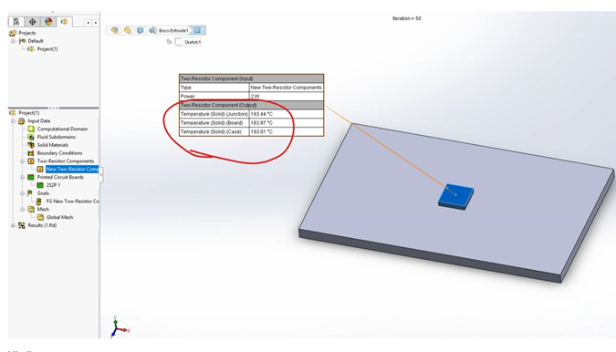
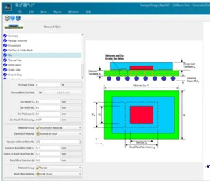
- Embedded IC models in CFD tools — Packages in Solidworks CFD (Electronics Cooling) and Simcenter Flotherm include library parts and modeling workflows to approximate real‑world assemblies.
Packages Keep Evolving—So Should Your Assumptions
From PBGA to FC‑BGA and beyond, packaging innovations alter thermal paths, material stacks, and heat‑spreading behavior. Every generation reshapes how heat travels from die to board or lid, changing how we size TIMs, heatsinks, and airflow. Treat package type as a design variable, not a constant.
Practical Workflow: From Spec to Concept
- Identify the major ICs early in the PCBA and collect thermal resistance data (θJB/θJC/θJA), package type, and power profiles (dynamic + static).
- Build a first‑order model (Two‑Resistor) to estimate junction temperature under baseline conditions; iterate power budgets and target temperature limits.
- Refine with CFD using vendor models or tool libraries (Solidworks CFD, Flotherm), incorporating realistic boundary conditions (airflow, neighboring components, board copper, heatsink, TIM).
- Plan mitigations: TIM selection, heatsink sizing, forced convection/fan tuning, heat pipes/vapor chambers/TEC where justified; revisit electrical impacts and reliability targets.
Key Takeaways
- Keep ICs cool to protect reliability and extend lifespan—thermal is not optional.
- Package type matters: different ICs exhibit different thermal behaviors; start with the datasheet.
- JEDEC values are estimates, not absolutes; validate with system‑level modeling and testing.
- Evolving packaging increases thermal complexity; keep assumptions current.
- Early engagement by mechanical engineers—during concept and layout—pays dividends in performance and cost.